Rectifier bridge output input wave voltage ac using without dc 230v transformer waveforms diode source block ltspice any arbitrary simulating Rectifier circuit diagram Full wave bridge rectifier || electronics 1 || bangla
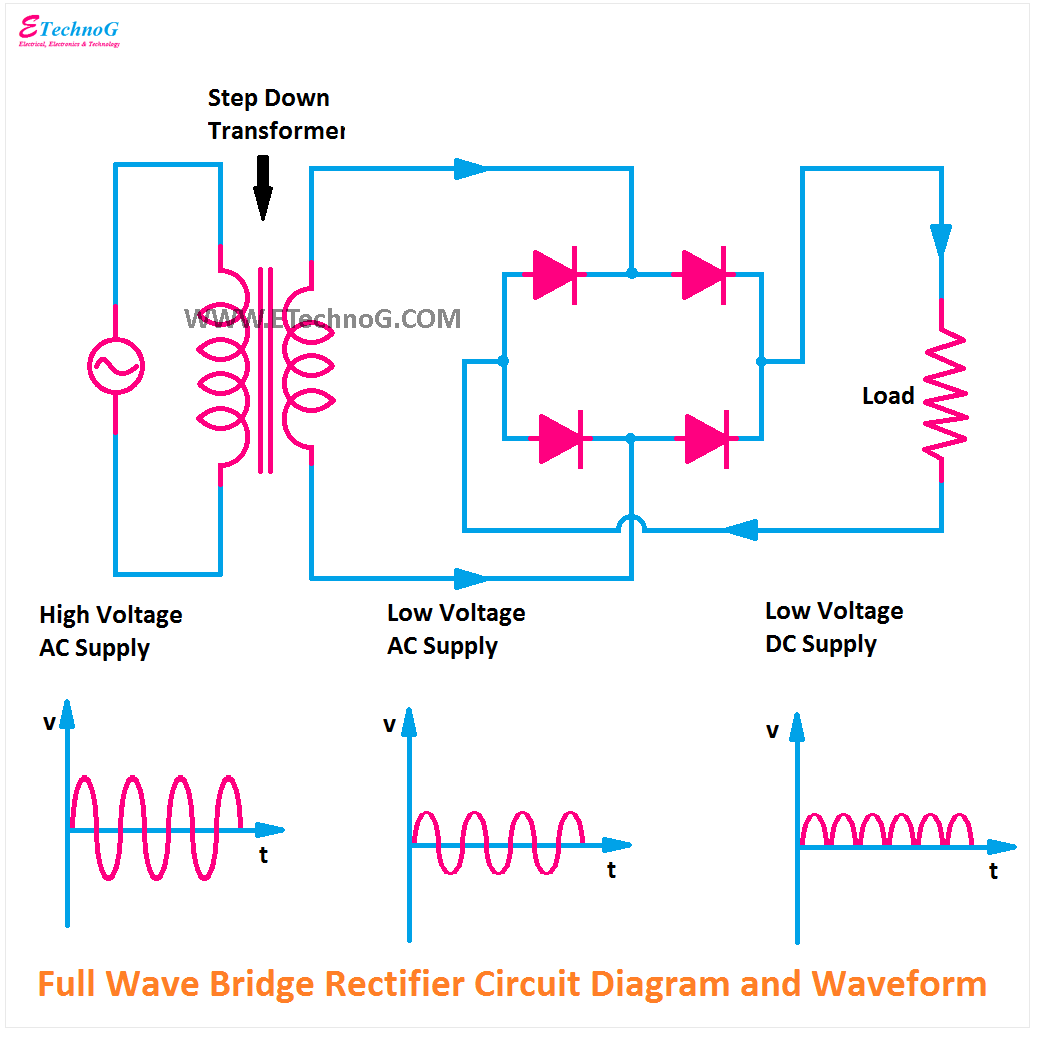
Full Wave Bridge Rectifier – Circuit Diagram and Working Principle
Rectifier waveform uncontrolled inductive resistive 5730 smd help. Full wave rectifier
Circuit analysis
Center-tapped full wave rectifier : definition, principle & benefitsWave bridge rectifier What is 3 phase rectifier ?Six-pulse full-bridge rectifier: firing angle vs output voltage.
Rectifier transformer tapped output waveform inputRectifier bridge working circuit components advantages electronicscoach Rectifier wave circuit bridge voltage output working transformer tapped centre across load advantages consistsFull-wave bridge rectifier (uncontrolled).

Rectifier wave bridge capacitor smoothing output waveform will standards electrical increase above dc
Full-wave rectifier output waveformRectifier waveform input Rectifier circuit diagramElectrical standards: full wave rectifier; full wave bridge rectifier.
Full wave bridge rectifier – circuit diagram and working principleRectifier wave waveform What is bridge rectifier ?Rectifier output dc wave bridge waveform circuit diagram voltage input principle working positive converts ac.

Wave rectifier bridge oscilloscope circuit understanding help diodes analysis
Rectifier bridge circuit diagram phase half pulse six wave output voltage diode angle rectification firing eevblog vs each figure diodesRectifier wave waveform output electronics tutorials gif Rectifier circuit waveform inputThe full-wave bridge rectifier.
Wave rectifier pulsating convertsRectifier tapped waveforms centre equations principle watelectrical Rectifier circuit diagram.


Rectifier Circuit Diagram | Half Wave, Full Wave, Bridge - ETechnoG

What is Bridge Rectifier ? - Working, Advantages & Disadvantages

Full-wave Rectifier Output Waveform | Basic Electronics Tutorials

circuit analysis - Help understanding a full wave bridge rectifier

Full Wave Bridge Rectifier – Circuit Diagram and Working Principle

Rectifier Circuit Diagram | Half Wave, Full Wave, Bridge - ETechnoG

5730 SMD help. - Page 2 - The Planted Tank Forum

Electrical Standards: Full wave rectifier; Full wave bridge rectifier
Full-Wave Bridge Rectifier (Uncontrolled) - Working, Construction, With