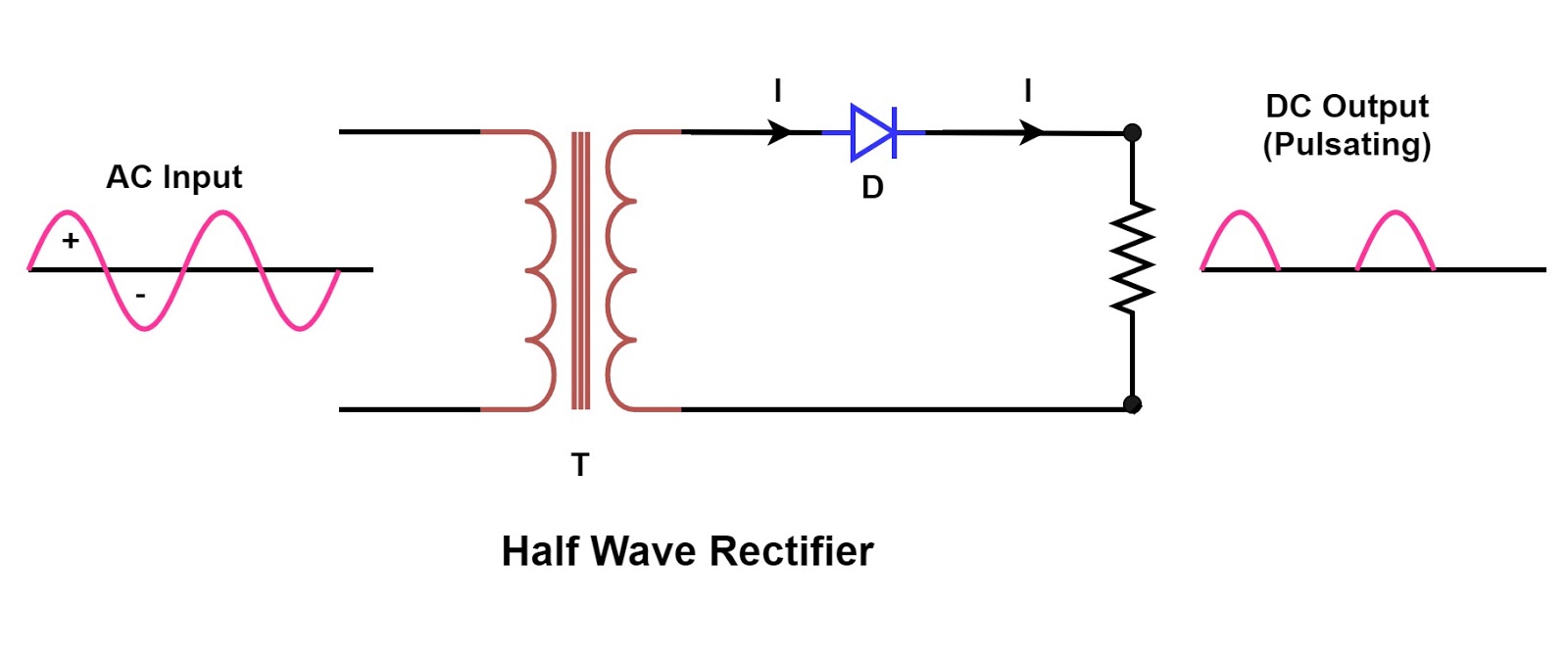
Rectifier circuit diagram Rectifier resistive transformer menghitung kebutuhan Rectifier phase single controlled wave motor electric mode discontinuous figure
Question:- (a) In the following diagram, is the junction diode forward
Rectifier transformer tapped output waveform input Rectifier wave bridge circuit diagram diode working simple draw operation diodes contents its works reverse circuits four Full-wave rectifier circuit with resistive load.
Question:- (a) in the following diagram, is the junction diode forward
Single phase half wave rectifier- circuit diagram,theory & applicationsSingle-phase, full-wave,controlled rectifier (electric motor) .
.


Question:- (a) In the following diagram, is the junction diode forward

Single Phase Half Wave Rectifier- Circuit Diagram,Theory & Applications

SINGLE-PHASE, FULL-WAVE,CONTROLLED RECTIFIER (Electric Motor)

Rectifier Circuit Diagram | Half Wave, Full Wave, Bridge - ETechnoG